
Features
- 20A or 25A switching capability
- Surge voltage up to 6kV (between coil and contacts)
- Explosion-proof products available

File No.:E75887

File No.:R 50267950

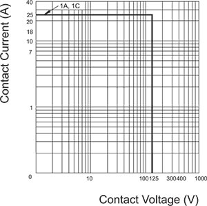
Contact Ratings
| Contact Arrangement | 1A, 1B, 1C | |
|---|---|---|
| Contact Resistance | ≤100mΩ(1A 24VDC) | |
| Contact Material | AgSnO, AgSnOIn | |
| Contact Rating (Resistive) | N.O.:20A/277VAC N.C.:16A/125VAC | N.O.:25A/125VAC 17A/277VAC N.C.:20A/125VAC |
| Max. Switching Voltage | 400VAC | 400VAC(NO) |
| Max. Switching Current | 20A | 25A |
| Max. Switching Power | 5540VA | 4709VA |
| Mechanical Life | 1×10⁷ operations | |
| Electrical Life | See more details at “safety approval ratings” | |
Characteristics
| Insulation Resistance | 100MΩ (at 500VDC) | |
|---|---|---|
| Dielectric Strength | Between coil & contacts | 2500VAC(PLT)/3500VAC(PLT-E) 1min |
| Between open contacts | 1000VAC 1min | |
| Surge voltage(between coil & contacts) | 6kV(1.2×50μs) | |
| Creepage(between coil & contacts) | ≥4.8mm(PLT), ≥7.3mm(PLT-E) | |
| Clearance(between coil & contacts) | ≥4.8mm(PLT), ≥7.3mm(PLT-E) | |
| Operate time (at nomi. volt.) | ≤10ms | |
| Release time (at nomi. volt.) | ≤5ms | |
| Humidity | 5%~85% RH | |
| Operation temperature | -40°C~+105°C | |
| UL Class B/F | Insulation System Class B/F | |
| Shock Resistance | Functional | 98m/s2 |
| Destructive | 980m/s2 | |
| Vibration resistance | 10Hz to 55Hz 1.5mm DA | |
| Unit weight | Approx. 14g | |
| Construction | Sealed Type, Dust Cover Type, Flux Tight Type | |
Notes:
1) The data shown above are initial values.
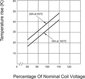
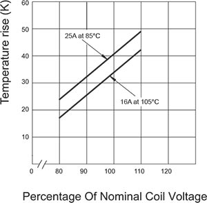
2) Please find coil temperature curve in the characteristic curves.
Ordering Information
| PLT | F | 1C | 20 | DC24 | K | E – | 1 – | XXXX |
|---|---|---|---|---|---|---|---|---|
| Model | F:Class F Blank:Class B | Contact Arrangement: 1A=1 Form A;1B=1 Form B 1C=1 Form C | Contact Rating: 20=20A(Standard Pin) 25=25A(Wide Pin) | Coil Voltage | Contact Gap: K=1mm(Form A only) R=2mm(Form A only) Blank:0.4-0.45mm | E:E Type Lead Pins Blank:Standard Pins | 1:Dust Cover Type 2:Flux Tight Type Blank:Sealed Type | Customer Code |
Notes:
1. PC board assembled with dust cover type and flux tight type relays can not be washed and/or coated.
2. Dust cover type and flux tight type relays can not be used in the environment with dust, or H2S, SO2, NO2 or similar gaseous environment etc.
Coil Data at 25°C
| Nominal Voltage VDC | Operate Voltage (Max.) VDC | Release Voltage (Min.) VDC | *Max. Allowable Voltage VDC | Coil Resistance Ω±10% | |
|---|---|---|---|---|---|
| 20A | 25A | ||||
| 3 | 2.25 | 0.3 | 3.9 | 25 | 20 |
| 5 | 3.75 | 0.5 | 6.5 | 70 | 55 |
| 6 | 4.50 | 0.6 | 7.8 | 100 | 80 |
| 9 | 6.75 | 0.9 | 11.7 | 225 | 180 |
| 12 | 9.00 | 1.2 | 15.6 | 400 | 320 |
| 18 | 13.50 | 1.8 | 23.4 | 900 | 720 |
| 24 | 18.00 | 2.4 | 31.2 | 1600 | 1280 |
| 48 | 36.00 | 4.8 | 62.4 | 6400 | 5120 |
Note:
“*Max Allowable Voltage”: The relay coil can endure max allowable voltage for a short period time only.
Coil
| Coil Power | 20A:360mW 25A:450mW |
|---|
Safety Approval Ratings
| UL&CUL | Non-Cd Contact (20A) | N.O.:20A 277VAC, G.P., 6×10³ OPS(40°C) N.O.:10A 120VAC, 3×10⁴ OPS(40°C) N.O.:5A 240VAC, 1×10⁵ OPS(40°C) N.O.:3A, 10A Inrush, 24VAC Pilot duty, 3×10⁴ OPS(40°C) N.O.:1A, 10A Inrush, 240VAC Pilot duty, 1×10⁵ OPS(40°C) N.O.:1.7A, 17A Inrush, 40VAC Pilot duty, 1×10⁵ OPS(40°C) N.O.:3.8FLA, 22.8 LRA, 120VAC HP, 1×10⁵ OPS(40°C) N.O.:3.6FLA, 21.6 LRA, 240VAC HP, 3×10⁴ OPS(40°C) N.O.:1.9FLA, 11.4 LRA, 240VAC HP, 1×10⁵ OPS(40°C) N.O.:8A 120VAC TV,25×103 OPS(40°C) N.O./N.C.:1/2HP 120VAC, 6×10³ OPS(40°C) N.O./N.C.:1/2HP 240VAC, 6×10³ OPS(40°C) N.C.:16A 125VAC, G.P., 6×10³ OPS(40°C) N.C.:10A 120VAC, 3×10⁴ OPS(40°C) N.C.:1.7A, 17A Inrush, 240VAC Pilot duty, 3×10⁴ OPS(40°C) N.C.:3.6FLA, 21.6 LRA, 240VAC HP, 3×10⁴ OPS(40°C) N.C.: 1000W 120VAC Tungsten, 1×10⁴ OPS(40°C) N.C.:3A 277VAC Electronic Ballast, 6×10³ OPS(40°C) N.C.:5A 277VAC Electronic Ballast, 6×10³ OPS(40°C) |
|---|---|---|
| Non-Cd Contact (25A) | N.O.:25A 125VAC, G.P., 6×10³ OPS(40°C) N.O.:17A 277VAC, G.P., 6×10³ OPS(40°C) N.O.: 1500W 277VAC Ballast, 6×10³ OPS(40°C) N.O.:1700W 120VAC Tungsten, 6×10³ OPS(40°C) N.C.:20A 125VAC, G.P., 6×10³ OPS(40°C) N.C.: 1500W 277VAC Ballast, 6×10³ OPS(40°C) N.C.:1700W 120VAC Tungsten, 6×10³ OPS(40°C) | |
| TüV | Non-Cd Contact (20A) | N.O.:16A 250VAC, 1×10⁴ OPS N.C.:10A 250VAC, 1×10⁴ OPS N.O.:16A 250VAC; N.C.:10A 250VAC, 1×10⁴ OPS |
NOTES:
1. All values without specified temperature are at 25°C.
2. The above lists the typical loads only. Other loads may be available upon request.
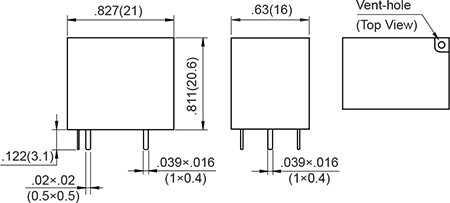
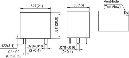
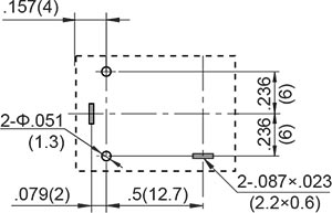
OUTLINE DIMENSIONS, WIRING DIAGRAM AND PC BOARD LAYOUT. Unit: inch(mm)
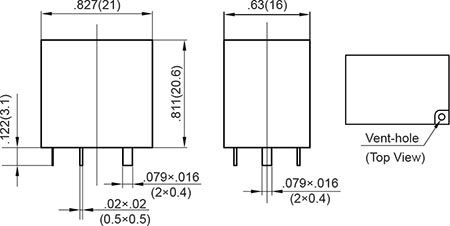
Outline Dimensions
20A
Standard Pins
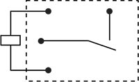
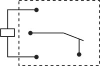
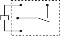
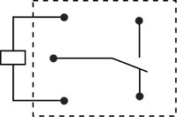
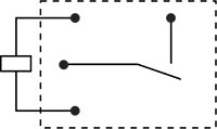
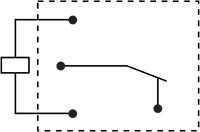
Wiring Diagram
(Bottom view)
1 Form A

1 Form B

1 Form C

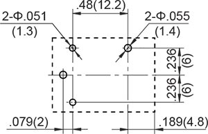
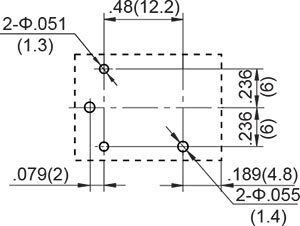
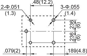
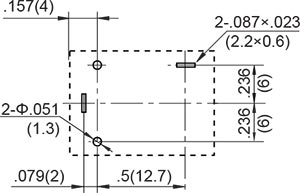
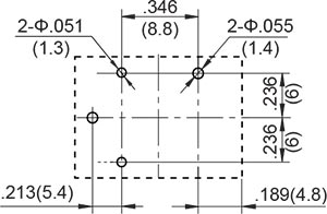
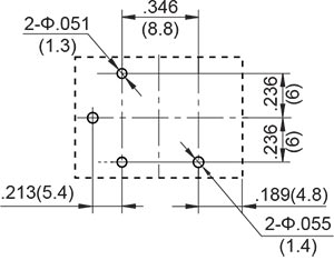
PCB Layout
(Bottom view)
1 Form A
1 Form B
1 Form C
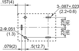
Outline Dimensions
25A
Standard Pins
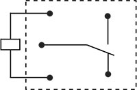
Wiring Diagram
(Bottom view)
1 Form A
1 Form B
1 Form C

PCB Layout
(Bottom view)
1 Form A
1 Form B
1 Form C
Outline Dimensions
20A
E Type Lead Pins

Wiring Diagram
(Bottom view)
1 Form A
1 Form B

1 Form C
PCB Layout
(Bottom view)
1 Form A
1 Form B
1 Form C

Outline Dimensions
25A
E Type Lead Pins
Wiring Diagram
(Bottom view)
1 Form A
1 Form B
1 Form C
PCB Layout
(Bottom view)
1 Form A
1 Form B
1 Form C
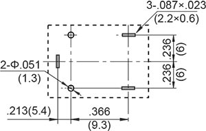
* The tolerance without indicating for PCB layout is always ±0.1mm.
Unless otherwise specified tolerances are:
| ≤1mm | >1mm and ≤5mm | >5mm |
| ±0.2mm | ±0.3mm | ±0.4mm |
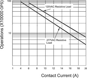
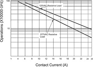
CHARACTERISTIC CURVES
20A
Max. Switching Power

Endurance Curve (N.O.)
Coil Temperature Rise
25A
Max. Switching Power
Endurance Curve (N.O.)
Coil Temperature Rise
PACKAGING SPECIFICATION
| BLISTER BOX | OUTER CARTON | OUTER CARTON SIZE |
|---|---|---|
| 30PCS | 1000PCS | L540mm*W200mm*H165mm |
APPLICATION GUIDELINES
Automatic Soldering
* Flow solder is the optimum method for soldering.
* Adjust the level of solder so that it does not overflow onto the top of the PC board.
* Unless otherwise specified, solder under the following conditions depending on the type of relay.
| Preheat time 20°C-100°C | Rising slope 20°C-120°C | Decreasing slope Peak-150°C | Welding temperature 255°C-265°C |
|---|---|---|---|
| 90±5 seconds | <3°C/s | <4°C/s | 3~5s |
Hand Soldering
* Keep the tip of the soldering iron clean.
| Solder lron | 30W or 60W |
|---|---|
| lron Tip Temperature | Approx. 350°C 662°F |
| Solder Time | Within approx. 3 seconds |
* Immediate air cooling is recommended to prevent deterioration of the relay and surrounding parts due to soldering heat.
* Although the sealed type relay can be cleaned, avoid immersing the relay into cold liquid
(such as washing solvent) immediately after soldering. Doing so may deteriorate the sealing performance.
Discard the dropped product
![]()