Hasco Relay’s Reed Switches are designed for long life and reliability. Each reed switch can sit idle for years without increased contact resistance.
HCH Reed Switches
Specifications
File No.:E75887 |  |  |  |  | |
| HCH25 | HCH211 | HCH219 | HCH229 | ||
|---|---|---|---|---|---|
Electrical Ratings | |||||
| Contact Form | A | A | A | A | |
| Contact Rating Watt-max. | 20 | 10 | 10 | 50 | |
| Voltage [V] | Switching Vdc-max. | 200 | 200 | 200 | 265Vac rms (250Vdc) |
| Breakdown Vdc-min. | 250 | 250 | 250 | 750 | |
| Current [A] | Switching A-max. | 1.0 | 0.5 | 0.5 | 1.0 |
| Carry A-max. | 1.2 | 1.0 | 0.8 | 2.5 | |
| Resistance [Ω] | Contact,Initial Ω-max. | 0.100 | 0.120 | 0.100 | 0.100 |
| Insulation Ω-min. | 1010 | 1012 | 1012 | 1010 | |
| Capacitance Contact pF-typ | 0.4 | 0.2 | 0.3 | 0.2 | |
| Temperature [°C] | Operating °C | -40 ~ +125 | -40 ~ +125 | -40 ~ +125 | -20 ~ +125 |
| Storage °C | -65 ~ +125 | -65 ~ +125 | -65 ~ +125 | -65 ~ +125 | |
Operating Characteristics | |||||
| Operating Time ms-max. | 0.7 | 0.5 | 0.6 | 0.75 | |
| Release Time ms-max. | 0.2 | 0.1 | 0.2 | 0.3 | |
| Shock 11ms 1/2 Sine Wave G-max. | 100 | 100 | 100 | 100 | |
| Vibration 50-2000 Hertz G-max. | 30 | 30 | 30 | 30 | |
| Resonant Frequency Hz-typ | 6250 | 8500 | 9500 | 2100 | |
Magnetic Characteristics | |||||
| Pull-in Range Ampere Tums | 17-38 | 10-25 | 10-25 | 22-43 | |
| Miniature CD | Sub-Miniature | Sub-Miniature | Miniature HV | ||

Specifications
File No.:E75887 |  |  |  |  | |
| HCH551 | HCH2210 | HCH2210V | HCH2212 | ||
|---|---|---|---|---|---|
Electrical Ratings | |||||
| Contact Form | C | A | A | A | |
| Contact Rating Watt-max. | 5 | 50 | 10 | 20 | |
| Voltage [V] | Switching Vdc-max. | 175 | 200 | 200 | 200 |
| Breakdown Vdc-min. | 200 | 300 | 2000 | 250 | |
| Current [A] | Switching A-max. | 0.25 | 1.5 | 0.5 | 1.0 |
| Carry A-max. | 1.5 | 3.0 | 1.3 | 1.0 | |
| Resistance [Ω] | Contact,Initial Ω-max. | 0.100 | 0.100 | 0.100 | 0.100 |
| Insulation Ω-min. | 106 | 1010 | 1012 | 1012 | |
| Capacitance Contact pF-typ | 1.0 | 0.2 | 0.2 | 0.4 | |
| Temperature [°C] | Operating °C | -40 ~ +125 | -40 ~ +125 | -75 ~ +125 | -40 ~ +125 |
| Storage °C | -65 ~ +125 | -65 ~ +125 | -75 ~ +125 | -65 ~ +125 | |
Operating Characteristics | |||||
| Operating Time ms-max. | 0.7 | 0.75 | 0.75 | 0.6 | |
| Release Time ms-max. | 1.0 | 0.3 | 0.3 | 0.2 | |
| Shock 11ms 1/2 Sine Wave G-max. | 50 | 100 | 100 | 100 | |
| Vibration 50-2000 Hertz G-max. | 30 | 30 | 30 | 30 | |
| Resonant Frequency Hz-typ | 11000 | 2100 | 3200 | 6250 | |
Magnetic Characteristics | |||||
| Pull-in Range Ampere Tums | 15-30 | 22-43 | 17-38 | 17-38 | |
| Miniature Changeover | Miniature Power | Miniature HV | Sub-Miniature | ||
Specifications
File No.:E75887 |  |  |  | ||
| HCH9215 | HCH9216 | HCH50WD | |||
|---|---|---|---|---|---|
Electrical Ratings | |||||
| Contact Form | A | A | A | ||
| Contact Rating Watt-max. | 10 | 10 | 50 | ||
| Voltage [V] | Switching Vdc-max. | 200 | 200 | 200 140 | |
| Breakdown Vdc-min. | 250 | 250 | 300(400) | ||
| Current [A] | Switching A-max. | 0.5 | 0.5 | 1.0,0.7 | |
| Carry A-max. | 1.2 | 1.2 | 3.0,2.1 | ||
| Resistance [Ω] | Contact,Initial Ω-max. | 0.100 | 0.100 | 0.100 | |
| Insulation Ω-min. | 1010 | 1010 | 1010 | ||
| Capacitance Contact pF-typ | 0.2 | 0.2 | 0.2 | ||
| Temperature [°C] | Operating °C | -40 ~ +125 | -40 ~ +125 | -40 ~ +125 | |
| Storage °C | -65 ~ +125 | -65 ~ +125 | -65 ~ +125 | ||
Operating Characteristics | |||||
| Operating Time ms-max. | 0.6 | 0.6 | |||
| Release Time ms-max. | 0.2 | 0.2 | |||
| Shock 11ms 1/2 Sine Wave G-max. | 100 | 100 | |||
| Vibration 50-2000 Hertz G-max. | 30 | 30 | |||
| Resonant Frequency Hz-typ | 3900 | 5200 | |||
Magnetic Characteristics | |||||
| Pull-in Range Ampere Tums | 12-38 | 10-30 | |||
| Sub-Miniature | Sub-Miniature | ||||
OKI Reed Switches
HASCO is a MASTER Value-Added Distributor of OKI Reed Switches. Ideal reed switch applications include liquid level sensors, magnetic contacts, proximity reed devices and reed relays. These reed switches are designed for long life and feature the ability to remain idle for years without increased contact resistance.
Specifications
File No.:E75887 | 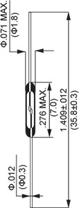 |  |  |  | ||
| ORD213 | ORD211 | ORD324 | ORD228 | |||
|---|---|---|---|---|---|---|
| Electrical Characteristics | Contact | 1A | 1A | 1A | 1A | |
| Pull-in Available in ±5 AT ranges | 10 ~ 40 | 10 ~ 40 | 10 ~ 50 | 10 ~ 50 | ||
| Drop-out | [AT] min. | 5 | 5 | 5 | 5 | |
| Contact resistance(Initial) | [mΩ] max. | 200 | 100 | 100 | 100 | |
| Breakdown voltage | [DCV] min. | 150 | 150 | 200 | 200 | |
| Insulation resistance | [Ω] min. | 109 | 109 | 1010 | 109 | |
| Electrostatic capacitance | [pF] max. | 0.4 | 0.2 | 0.3 | 0.3 | |
| Contact rating | [VA,W] | 1.0 | 1.0 | 10 | 10 | |
| Maximum switching voltage | [V] | AC24 / DC24 | AC24 / DC24 | AC140 /DC200 | AC110 / DC100 | |
| Maximum switching current | [A] | DC 0.1 | DC 0.1 | DC 0.5 | DC 0.4 | |
| Maximum carry current | [A] | 0.3 | 0.3 | 1.0 | 1.0 | |
| Operating Characteristics | Operating time | [ms] max. | 0.3 | 0.3 | 0.3 | 0.3 |
| Bounce time | [ms] max. | 0.3 | 0.3 | 0.3 | 0.3 | |
| Release time | [ms] max. | 0.05 | 0.05 | 0.05 | 0.05 | |
| Resonant frequency | [Hz] | 1100 ± 500 | 7500 ± 500 | 5000 ± 400 | 5300 ± 300 | |
| Maximum operating frequency | [Hz] | 500 | 500 | 500 | 500 | |
| Standard coil | Coil resistance | [Ω] | 600 | 600 | 450 | 450 |
| No. of turns | [T] | 5000 | 5000 | 5000 | 5000 | |
| Dimensions | [mm] | Φ3.3 × 10 | Φ3.3 × 10 | Φ3.7 x 15 | Φ3.7 × 15 | |
| Type No. | 8 | 8 | 6 | 6 | ||
| Features (Contact material) | Ultra-miniature (RH) | Ultra-miniature (RH) | General purpose miniature (RH) | General purpose miniature (RH) | ||
Specifications
File No.:E75887 |  |  | 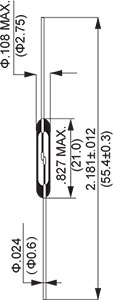 |  | ||
| ORD9215 | ORD221 | ORD229 | ORD2210 | |||
|---|---|---|---|---|---|---|
| Electrical Characteristics | Contact | 1A | 1A(offset) | 1A | 1A | |
| Pull-in Available in ±5 AT ranges | 10 ~ 50 | 1 ~ 40 | 15 ~ 40 | 15 ~ 60 | ||
| Drop-out | [AT] min. | 4 | 5 | 6 | 7 | |
| Contact resistance(Initial) | [mΩ] max. | 150 | 100 | 100 | 100 | |
| Breakdown voltage | [DCV] min. | 200 | 200 | 600 | 250 | |
| Insulation resistance | [Ω] min. | 109 | 109 | 1010 | 1010 | |
| Electrostatic capacitance | [pF] max. | 0.3 | 0.3 | 0.5 | 0.5 | |
| Contact rating | [VA,W] | 10 | 10 | 50 | 50 | |
| Maximum switching voltage | [V] | AC110 / DC100 | AC100 / DC100 | AC300 / DC350 | AC70(VA) / DC50(W) | |
| Maximum switching current | [A] | 0.3 | DC 0.3 | DC 0.5 | AC0.7 / DC1.0 | |
| Maximum carry current | [A] | 1.0 | 1.0 | 2.5 | 2.5 | |
| Operating Characteristics | Operating time | [ms] max. | 0.4 | 0.3 | 0.6 | 0.5 |
| Bounce time | [ms] max. | 0.4 | 0.5 | 0.5 | 0.5 | |
| Release time | [ms] max. | 0.05 | 0.5 | 0.05 | 0.05 | |
| Resonant frequency | [Hz] | 3700 ± 300 | 2750 ± 250 | 2500 ± 250 | 2500 ± 250 | |
| Maximum operating frequency | [Hz] | 500 | 500 | 500 | 500 | |
| Standard coil | Coil resistance | [Ω] | 450 | 450 | 500 | 500 |
| No. of turns | [T] | 5000 | 5000 | 5000 | 5000 | |
| Dimensions | [mm] | Φ3.7 × 15 | Φ3.7 × 15 | Φ4.6 × 21 | Φ4.6 × 21 | |
| Type No. | 6 | 6 | 3 | 3 | ||
| Features (Contact material) | General purpose miniature (RH) | Miniature offset (RH) | High breakdown voltage (RH) | High power (RH) | ||
Specifications
File No.:E75887 |  |  |  | ||
| ORD2211 | ORD2210V | ORT551 | |||
|---|---|---|---|---|---|
| Electrical Characteristics | Contact | 1A | 1A | 1C | |
| Pull-in Available in ±5 AT ranges | 15 ~ 60 | 20 ~ 60 | 10 ~ 30 | ||
| Drop-out | [AT] min. | 8 | 7 | 5 | |
| Contact resistance(Initial) | [mΩ] max. | 100 | 100 | 100 | |
| Breakdown voltage | [DCV] min. | 200 | 1000 | 200 | |
| Insulation resistance | [Ω] min. | 109 | 1010 | 109 | |
| Electrostatic capacitance | [pF] max. | 0.3 | 0.5 | 1.5 | |
| Contact rating | [VA,W] | 50 | 100 | 3 | |
| Maximum switching voltage | [V] | AC100 / DC100 | AC300 / DC350 | AC30 / DC30 | |
| Maximum switching current | [A] | 0.5 In rush 3A | DC 1.0 max. | DC 0.2 | |
| Maximum carry current | [A] | 2.5 | 2.5 max. | 0.5 | |
| Operating Characteristics | Operating time | [ms] max. | 0.6 | 0.5 | 1.0 |
| Bounce time | [ms] max. | 0.4 | 0.5 | (NC)1.5 / (NO)1.0 | |
| Release time | [ms] max. | 0.05 | 0.05 | 0.5 | |
| Resonant frequency | [Hz] | 4600 ± 500 | 2500 ± 250 | 6000 ± 4000 | |
| Maximum operating frequency | [Hz] | 500 | 500 | 200 | |
| Standard coil | Coil resistance | [Ω] | 450 | 450 | 550 |
| No. of turns | [T] | 5000 | 5000 | 5000 | |
| Dimensions | [mm] | Φ3.7 × 15 | Φ3.7 × 15 | Φ4.6 × 10 | |
| Type No. | 6 | 6 | 10 | ||
| Features (Contact material) | Lamp load 3.4W Low sound (RH) | Vacuum (RH) | Ultra- miniature transfer (RH) | ||
*Magnets also available, Available Cut and Bent as Well as on Reed.
Notes:
 1.Pull-in & drop-out were measured by using OKI standard coil.*This value of drop-out is prescribed when pull-in is over 20AT. When pull-in is less than 20AT, drop-out are 5 MIN & RLS/OP >0.7, Tolerance at measurement is ±2AT. (Fig.1)
2.Measurements are made by the four-terminal voltage reduction method where the 100AT excitation is given to the switch using the OKI standard coil to close the contacts, and 10mA current is applied.
3.This value varies depending on the pull-in value (contact gap). In this measurement, the pull-in value is about 20AT.(MIL-STD-202D METHOD 301)
4.Measurement is made by using a DC 100V super megger.(MIL-STD-202D METHOD 302)
5.The value shows the time required for the contacts to cause the first contact bounce after applying the voltage to the OKI standard test coil. The times is shown at top in Fig.2
 6.Bouncing is caused when the contact close. Bounce time means the time when opening and closing of the contacts are being repeated before the contacts are completely closed. Shown by T bounce.
7.Release time means the time from the morment the voltage applied to the test coil as removed to the moment the contacts open. Shown by Tris.
8.Resonant frequency is a vibrating frequency inherent to the reed switch. Avoid application of vibration at this frequency to the switch, otherwise it will cause misoperation.
9.The reed switch can be operated with a frequency higher than the maximum operating frequency. However, operation with such a frequency will often cause an endless chattering at the time of ON operation. It is recommended for the designer to take the maximum operationg frequency into consideration when designing systems and circuits.
10.Dimensions of standard coil.
A:Inner diameter of standard coil.
B:Length of standard coil.
11.If a shock of more than 30G is applied to a reed switch, the pull-in value of the switch will be often caused to change from the standard specification. Therefore, it is recommended not to use the reed switch which has been given such a shock.
12.If a vibration of more than 1 kHz is applied to a reed switch, even a very small acceleration to it will easily cause the switch to misoperate to close due to its resonant frequency.
13.In practice the reed switch can operate beyond the specified range. In case of magnet driving. however, some magnets show decrease of magnetic flux even at the lowest temperature of the range depending on their temperature characteristics. There fore, it is recommended to consider the range as a general guide line.
14.The actual tensile strength is more than 5 kg (breakdown). However, considering the lead not to get out of position, the value for the static load is shown here.
| Environmental Characteristics Table 2 | |||
| Characteristics(Common to All Types) | Test Conditions | Notes | |
| Shock | Shall not misoperate with shock of 30G(11ms) applied | MIL-STD-202E METHOD 213B | 13 |
| Vibration | Shall not misoperate with max. 20G(10-55Hz) | MIL-STD-202E METHOD 210A | 14 |
| Temperature range | Shall be operational in the range of -40~125°C | MIL-STD-202E METHOD 107D | 15 |
| Lead tensile strength | Shall withstand against 2Kg static load | MIL-STD-202E METHOD 211A | 16 |
Our reed switches are available in multiple styles and housing types in either SMT or through hole designs. We can custom bend and produce any reed configuration either bare or in a housing. Simply send us your specs for us to quote.
Please note: HASCO can produce and/or stuff any PC board with a reed switch or relay in house at our state of the art production facility.


![]()