
Main Points to Select Suitable Relay
A relay may meet with a variety of ambient conditions during actual usage. In order to avoid unexpected failure in result, testing over practical range under actual operating condition is required. For proper use of relays, the characteristics of the selected relay should be well known, and the conditions of relay use has to be investigated to determine whether they are matched to the environmental conditions, In addition, the coil conditions, contact conditions, and the ambient conditions for the relay that is actually used must be sufficiently known in determining the relay specififcations. The table below shows a summary of points of consideration for relay selection. It may be used as a reference for investigation of items and points of caution.
Table 2. Main Ponts to Select Relays
| Item | Specification Points | Consideration Points |
|---|---|---|
| Contact | Contact arrangement | Contact forms, number of poles, Contact sequence |
| Contact load | Level of load,AC or DC,resistive or indicative or capacitive, counter voltage of inductive load | |
| Contact material | Contact material should be matched to the level of load | |
| Life | Number of operations, Frequency in switching | |
| Coil | Coil voltage | Nominal voltage, power source ripple |
| Pick-up and Drop-out voltage | Fluctuation in supply voltage, Rise in Pick-up and Drop-out voltage due to the coil resistance rise | |
| Coil resistance | Power consumption of coil temperature rise according to the coil temperature rise | |
| Temperature rise | Ambient temperature and coil temperature rise according to the applied voltage. | |
| Insulation | Dielectric strength | Do specifications of the relays match that required in the equipment? |
| Surge withstand voltage | ||
| Insulation resistance | ||
| Environment | Ambient temperature and humidity | Range of ambient temperature and humidity in the use location. |
| Vibration and shock | Level of vibration and shock in the use location. | |
| Ambient atmophere | No presence of gas which may cause contact failure. | |
| Others
| Mounting method | The method of flux coating, soldering, washing and mounting? |
| Cover | Material of cover (compatibility with washing solution) | |
| Relay construction | Sealed or non-sealed type relays. | |
| Special condition | Are there any special conditions? |
Contact
(1) Contact load
The phenomena in the contacts of relays greatly vary depending on contact load level such as kind of load and current level as
well as contact material and size, opening speed and contact bounce.
*Switching current
AC current is alternately reduced to zero but DC current is not, so the arc discharge current at breaking of load current is hard to be extinguished for DC current.
Therefore the duration of the arc discharge is longer in DC circuit than AC circuit and the maximum DC switching current is smaller than AC load.
*Resistive load
Resistive load is a standard load in life tests and the contact ratings in catalogue are usually specified with resistive load.
In resistive load circuit, it is assumed that there is no inrush or counter breaking current on switching of loads.
*Inductive load
Inductive loads such as electromagnetic relay, solenoids and motors easily generate a high counter voltage between their coils and cause arc discharge across the relay contacts.
Because the level of inductive load is affected by the load current and the power factor (coso), the life is decreased when the power factor is lowered.
In circuit with load such as motor, solenoid, transformer and others, an inrush current of several times larger than the steady current is generated at the time of connecting the load.
It is necessary to select the contact that has a sufficient capacity for the conditions.
*Capacitive load
In a capacitive load circui, an inrush current of 20 to 40 times large than the steady state current is produced. A surge suppressor should be used to prevent contact welding.
(2) Contact material
Relay contacts must be made from material that allows contact resistance to be low and stable, that is not quickly worn by the arc, and that has a high fusing point. At present there is no material that meets these conditions, and it appears unlikely that one will be found in the near future.
(3) Low level circuit
Circuits with several volts and several mA or less are called low-level circuits. At low levels, silver contacts form an oxide or sulfide film on their surface under certain conditions, which makes contact resistance unstable. If the circuit impedance is high, although the high contact resistance itself does not cause problems, the noise is easily produced. To maintain stability of contact resistance in a sulfurating atmosphere, contact of gold overlayed on silver-palladium are effective.
Table 3. Typical load and Inrush Current
| Kind of Load | Inrush current |
|---|---|
| Resistive load | Steady state current |
| Solenoid load | 10-20 times of the steady state current |
| Motor load | 5-10 times of the steady state current |
| Incandescent lamp load | 10-15 times of the steady state current |
| Mercury lamp load | Approx.3 times of the steady state current |
| Condenser load | 20-40 times of the steady state current |
| Transformer load | 5-15 times of the steady state current |
| Contactor load | 3-10 times of the steady state current |
Coil
(1) Coil voltage of DC relay
For the operation of DC relays, standards exist for power source voltage, with DC voltage standard set at DC5,6,9,12,24 and 48. Because of the gradual increase or decrease of the current impressed on the coil causing possible delay in movement of the contacts, there is a possibility that the specified contact capacity may not be satisfied.
So, consideration should be given to the method of applying voltage on the coil.
(2) Power source fluctuation

As a power source for DC relays, a battery or either a half or full wave rectifier circuit with smoothing capacitor is used.
The characteristics with regard to the excitation voltage of the relay will change depending on the type of power source, and thus, in order to display stable characteristics, the most desirable method is perfect DC.
In the case of ripple included in the DC power source, if the smoothing capacitor is too small, humming develops and unsatisfactory condition is produced, due to the influence of the ripple.
This ripple is calculated using the formula described in Fig.4 and it is necessary to give consideration to use of a power source with less than a 5% ripple.
Fig.4 Ripple factor of rectifier circuit
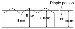
Ripple factor=![]()
E max.=Maximum value of ripple portion
E min.=Minimum value of ripple
E mean=Average value of ripple portion
(3) Coil resistance
The resistance of coil is specified according to the nominal voltage of the relay. Generally, the nominal value of coil resistance is that at 20°C(68°F) and the allowable range is limited to within ±10%. The resistance/temperature relationship for copper wire is about 4‰ for 1°C, and with this ratio, the coil resistance increases.
Performance
(1) Contact resistance
(a) Contact wipe
The contact resistance of clean surface is extremely low, such as several mΩ. In practice, some kind of film is formed on to almost all of the contact surfaces and the contact resistance varies depending on the properties of that film.
To clean such film and stabilize contact resistance, distance of the contact wipe is increased.
When contacts open and close, the contacted surfaces slid together, thus effecting a breakage of nonconductive film formed on the contact surfaces.
(b) Contamination of contact surface
The Possible causes of contamination that effects increases in contact resistance are as follows.
*Adherence of fiber, scale and particles of plastic mold, etc.
*Adherence of silicone oxides.
*Adherence and deposits of non-conducting material produced through a chemical reaction with the gas absorbed onto the contact face.
*Adherence and deposits of carbon powders produced at contact surface
Oxidation and sulfuration of metallic powders on the contact surface.
(c) A bifurcated contact is contaminated
The bifurcated spring is cut deeply enough and separated so as to provide a good independence in a contact even when some insulating particle is trapped between contact on one side.
In this case, the contact of the other side can serve to maintain a good contact, with the sufficient mechanical independence between the two members. So, the bifurcated contacts have successfully reduced contact failures.
(d) Sealed relay
Sealed relays are available. This feature excludes the ingress of organic gases and dust in atmosphere and allows immersion cleaning.
When a sealed type relays switches the load in the presence of organic gases inside relay, it produces carbon powders on the contacts which create rise of contact resistance and acceleration of contact resistance and acceleration of contact consumption. In order to avoid such problems, the constituent components are annealed for physical and chemical stability. This annealing process drives off residual volatiles in the plastics, insuring a contaminant free environment inside the sealed relay, resulting in more stable contact resistance over life.
(2) Coil
*Nominal Coil Voltage (Rated Coil voltage)
A single value voltage intended by design to be applied to the coil or input.
*Pick-up Voltage (Pull-in Voltage or Must Operate Voltage)
When the voltage on an unoperated relay is increased, the value at or below which all contacts must function (transferred). The pick-up voltage is generally assigned to 70% of nominal coil voltage so that the relay can function without failure owing to fluctuation of voltage supplied, ambient temperature raise and irregularity of coil resistance.
*Drop-out Voltag (Release or Must Release Voltage)
When the voltage on an operated relay is decreased, the value at or above which all contacts must revert to their unoperated position. The drop-out voltage is generally assigned to 10% of nominal coil voltage. Figure 5 shows the relationship between Pick-up Voltage and Drop-out Voltage.
Fig.5 Relationship of Relay Performance

(3) Coil temperature rise
When voltage is applied to a coil, its temperature increases due to juele heat. Coil temperature rise can be calculated from the temperature coefficient of the copper wire by measuring the coil resistance.
The coil temperature rise can be obtained by the next expression.
![]()
where, T: Coil temperature rise (°C)
TI: Initial ambient temperature (°C)
T2: Coil temperature after the test (°C)
Ta: Ambient temperature after the test (°C)
RI: Coil resistance at T1 °C (Ω)
R2: Coil resistance at T2 °C (Ω)
K: Constance (=235 for copper wire)
however, I T1 – Ta 1 ≤ 5 (°C)
Coil temperature rise
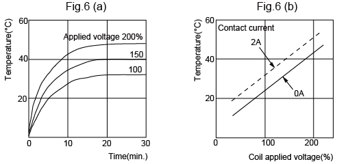
Figure 6 (a) shows the duration characteristics. Figure 6 (b) shows the voltage characteristics in a steady state at constant supply voltage.
(4) Hot coil and Cool coil
The coil temperature with no voltage applied on the coil is usually to be equal to the ambient temperalure. When voltage is applied to the coil, the coil temperature rises, increasing both coil resistance and pick-up voltage. The coil with it’s temperature rise due to voltage impression is called a Hot Coil. To the contrary, when no voltage is impressed on coil, the coil, temperature of which is equal to ambient temperature, is called a Cool Coil.
In general, the values for characteristics such as pick-up voltage, drop-out voltage and so on are measured at the ambient temperature of 20°C 68°F, Cool Coil conditions. For the Hot Coil, because of it’s pick-up voltage rise, these is a possibility that hat it may not operate under the same conditions as Cool Coil.Thus,care is required.
(5) Operating range
(a) Maximum continuous voltage
The maximum voltage that can be applied continuously to the coil without causing damage. When a voltage greater than the maximum continuous voltage is applied to the coil (layers may short) the coil may burn out, due to the temperature rise. Do not exceed the usable operating range shown in the Fig. 7.
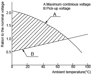
(b) Pick-up voltage
As the ambient temperature rises, the coil resistance increases, pick-up voltage. Figure 7, line B refers to the relationship. The upper portion of line-B in Fig.7 shows the range of voltage which can be applied to the coil. Line-A is maximum continuous voltage. Thus the relay operating range is the portion surrounded by line A and B.
In order to have stable operation of relay, the APP voltage and the ambient temperature should be in the operating range. If the ambient temperature increases, pickup voltages rises, while maximum continuous voltage decrease. Care is required.
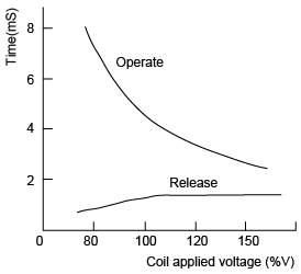
(6) Operate time and Release time
There is variation in Operate time and Release Time depending upon voltage/power applied to coil.
Figure 8 shows an example of relationship between Operate Time and Release Time. Figure 8 refers to the phenomenon that according to the fluctuation of coil impressed voltage, Operate Time greatly varies, while Release Time is small. To the extent of large coil imressed voltage, the Operate Time is rapid, but if it is too rapid, the make contact bounce time may be extended.
(7) Safety standards
Laws and regulations demand securing the safety of users from dangers such as electric shock and fire lying around household appliances and other consumer electric equipment or devices.
Major industrial countries across the world already have their own safety standards such as those under control of ‘The Electrical Appliance and Material Control Law’ in Japan, UL in U.S.A.,CSA in Canada, VDE in Germany, SEMKO in North Europe and BS in GB.
Ambient Environment
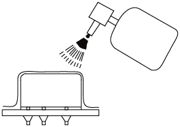
(1) Silicone compound atmosphere
Silicone compounds such as silicone rubber,silicone paint, silicone grease, etc. emit volatile silicone gas. Note that when silicone is used near relays, switching contacts in the presence of its gas causes silicon to adhere to the contacts and may result in contact failure. In this case, use a substitute that is not silicone based. If the use of silicone compound is inevitable, use a plastic-sealed relay.
(2) Influence of external magnetic field
When transformers, speakers or magnets are located near a relay the characteristics may change and faulty operations may result due to the strong magnetic field generated from the equipment.
The influence depends on the strength of the magnetic field and it should be checked at the installation. In such a case suitable measures such as magnetic shielding or selection of adequate in arrangement of relay should be taken so as to avoid problems.
Mounting of Relays
(1) Mounting direction
Mounting direction is important for optimum relay characteristics.
(2) Shock and vibration resistance
It is ideal to mount the relay so that the movement of contacts and armature is perpendicular to the direction of vibration or shock, as shown in Fig. 10.
Fig.10 Direction of relays

(3) Contact reliability
It is recommended to mount the relays so that the surfaces of its contacts are vertical and in Lipper location of relay inside. Such mounting methods prevent dirt and dust as well as scattered contact material (produced due to large loads from which arcs are generated) and powdered metal from adhering to them. Furthermore, it is not desirable to switch both a large load and a low level load with a single relay.
The scattered contact material produced when switching the low level load and may cause contact failure. Therefore, avoid mounting the relay with its low level load contacts located below the large load contacts.
(4) Adjacent mounting
When many relays are mounted close together, abnormally high temperature may result from the combined heat generated. Mount relays with sufficient spacing between them to prevent heat buildup, This also applies when a large number of bords mounted with relays are installed as in a card rack. Be sure the ambient temperature of the relays does not exceed the value listed in the catalog.
Relay Soldering and Washing Guidelines
| Process | Guidelines | ||||||||||||||||||||||||
|---|---|---|---|---|---|---|---|---|---|---|---|---|---|---|---|---|---|---|---|---|---|---|---|---|---|
1.Mounting of relay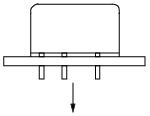 2.Flux coating 2.Flux coating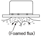 3.Preheating 3.Preheating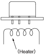 4.Soldering 4.Soldering 5.Cooling 5.Cooling 6.Washing 6.Washing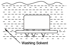 7.Coating 7.Coating
| *Avoid bending and terminals to make the relay self-clinching. Relay performance cannot be guaranteed if the terminals are bent.*Adjust the position of the PC board so that flux does not overflow onto the top of it. *Use rosin-based flux, which is non-corrosive and requires no washing. *Do not use Automatic Flux Coating Method to dust-cover type relays. *Do not overflow onto the top of PC Board, in such a case, the flux may even penetrate a flux-resistant type relay.*Be sure to preheat before soldering. *Preheating acts to improve solderability. *Preheat according to the following conditions.
*Note that long exposure to high temperatures (e.g. due to a malfunctioning unit) may affect relay characteristics. Automatic Soldering
Hand Soldering *Keep the tip of the soldering iron clean.
*Immediate air cooling is recommended to prevent deterioration of the relay and surrounding parts due to soldering heat. * Do not wash flux-resistant type relays and dust cover type relays by immersion. Table 6. Washing solvent compatibility chart for sealed relays
* If the PC board is to be coated to prevent the insulation of the PC board from deteriorating due to corrosive gases and high temperature, note the following. | ||||||||||||||||||||||||
Relay Terminology: Performance
(1) Operate (Set) time
Time from initial energization to the first opening of closed contact or first closing of open contact. This time does not include any bounce time. In case of latching relays, this is called “Set time”.(cf. Fig.1)
Fig.1 Typical time traces of relay
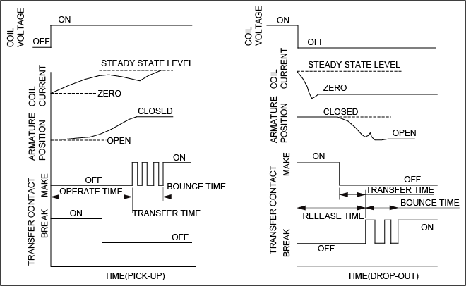
(2) Release (Reset) time
Time from initial de-energization of the relay coil to first opening of closed contact or first closing of open contact. This time does not include any bounce time. In case of latching relays, this is called “Reset time”.
This means the time from initial reverse energization of the coil to first opening of closed contact or first closing of open contact.(cf. Fig.1)
(3) Bounce time
Internally caused intermittent and undesired opening of closed contact or closing of open contacts of a relay.(cf. Fig.1)
(4) Dielectric strength
The maximum. allowable AC(RMS) voltage (50/60Hz) which may be applied between two specified test points, usually for 1 minute in duration. In general, the maximum leak current is 1 mA.
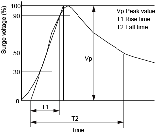
(5) Surge withstand voltage
The maximum allowable peak surge voltage which may be applied between two specified test points.
Usually, wave form of this test is specified indicating peak value, rise time and fall time.(cf. Fig.2) In FCC Part 66, T1=10 μS, Vp 1500V are specified.
Fig.2 Ware form of Surge test
(6) Insulation resistance
The resistance between all mutually insulated conducting sections of the relay. This value changes depending on the ambient temperature and humidity.
(7) Capacitance
The electrostatic capacitance between mutually insulated conducting sections of the relay. Usually this value is measured at 1 kHz.
(8) Life
- Mechanical life
The minimum number of operations which the relay can be operated under nominal conditions with no load on the contacts. - Electrical life
The minimum number of operations which the relay can be operated under nominal conditions with specified load on the contacts.
(9) Vibration resistance
The resistance to the vibration applicable to the relay. expressed as a displacement and frequency range.
- Functional
The vibration which can be applied to the relay during service without causing the openings of the closed contacts for more than the specified time. - Destructive
The vibration which can be allowed by the relay during shipping, installation, without damages and changes in its operating characteristics.
(10) Shock resistance
The resistance to the shock applicable to the relay, expressed as an acceleration in G.
- Functional
The shock can be applied to the relay during service without causing the openings of the closed contacts for more than the specified time. - Destructive
The shock which can be allowed by the relay during shipping, installation, without damage and changes in its operating characteristics.
(11) Temperature range
The range of ambient temperature in which the relay can be used without damages in its characteristics or functions.
(12) Safely standard
Standard for the prevention of electric shock hazards and fire accidents differs in content from country to country.
UL (U.S.A.) VDE (Germay) BS (G.B.)
SEMKO (Sweden) CSA (Canada)
(13) Structure of relays
Relays are classified in 4 types as Fig. 3 by the structure of terminals, cover and case, and mounting method of the relay.
Fig. 3 Structure of relays (Y:Yes N:No)
| Item | Dust cover Type | Flux Free Type | Sealed Type | Surface Mount Type |
|---|---|---|---|---|
| Structure | 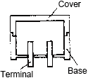 | 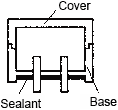 | 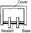 |  |
| Characteristics | Most basic construction and there is gap between cover and base, and between base and terminals. | Terminals are sealed with base by sealant. The joint level between cover and base is higher than the PC board surface. | All the gaps between case and base, base and terminals are sealed by sealant. | All the gaps between case and base, base and terminals are sealed by sealant. Terminals are formed in “L” shape intended to be soldered by reflow soldering. |
| Mounting Method | Insertion mounting | Insertion mounting | Insertion mounting | Surface mounting |
| Automatic Flux Coating | N | Y | Y | Y |
| Automatic Soldering | N | Y | Y | Y |
| Automatic Washing | N | N | Y(Note 1) | Y(Note 1) |
| Manual Soldering | N | Y | Y | – |
| Environmental Gas Resistance | N | N | Y(Note 2) | Y(Note 2) |
Note1:It is needed to select suitable washing solvent.
Note2:In explosive gas environment, use the metallic hermetic seal types.
![]()