

Features
- Multi contact arrangements: 2 Form C, 1NO+1NC(AB1), 1NO+1NC(AB2)
- Forcibly guided contacts according to EN50205
- 8A switching capability
- High insulation capability(1.2/50μs):10kV surge voltage between coil & contacts and 6kV between contact sets
- UL insulation system:Class F

File No.:E75887

File No.:R 50562547


Contact Ratings
| Contact Arrangement | 2C, AB1, AB2 |
|---|---|
| Forcibly guided contacts Type (according to EN50205) | AB1, AB2:Type A |
| 2C:Type B | |
| Contact Resistance | ≤100mΩ (1A 6VDC) |
| Contact Material | SiIver AIIoy |
| Contact Rating (Resistive) | 6A 277VAC/30VDC |
| Max. Switching Voltage | 400VAC/30VDC |
| Max. Switching Current | 8A |
| Max. Switching Power | 2216VA/240W |
| Mechanical Life | 1×10⁷ OPS |
| Electrical Life | 1×10⁵ OPS(1NO: 8A 277VAC/30VDC, Resistive Load, 85°C, 1s on and 9s off) 1×10⁵ OPS(1NC: 6A 277VAC/30VDC,Resistive Load, 85°C, 1s on and 9s off) |
Characteristics
| Insulation Resistance | 1000MΩ (at 500VDC) | |
|---|---|---|
| Dielectric Strength | Between coil & contacts | 4000VAC 1min |
| Between open contacts | 1500VAC 1min | |
| Between contacts sets | 3000VAC 1min | |
| Surge voltage | Between coil & contacts | 10kV(1.2/50μs) |
| Between contacts sets | 2.5kV(1.2/50μs) | |
| Between contacts sets | 6kV(1.2/50μs) | |
| Operate time (at nomi. volt.) | ≤15ms | |
| Release time (at nomi. volt.) | ≤10ms | |
| Humidity | 5% to 85% RH | |
| Operation temperature | -40°C~+85°C | |
| UL Class B/F | Insulation System Class B/F | |
| Shock Resistance | Functional | N.O.:98m/s2 N.C.:49m/s2 |
| Destructive | 980m/s2 | |
| Vibration resistance | N.O.: 10Hz to 55Hz 1.6mm DA 55Hz to 200Hz 98m/s2 N.C.: 10Hz to 55Hz 0.4mm DA | |
| Creepage distance | Between coil & contacts | 8mm |
| Between contacts | 5.5mm | |
| Clearance distance | Between coil & contacts | 8mm |
| Between contacts | 5.5mm | |
| Unit weight | Approx. 20g | |
| Construction | Flux Tight Type, Sealed Type | |
Notes:
1) The data shown above are initial values.
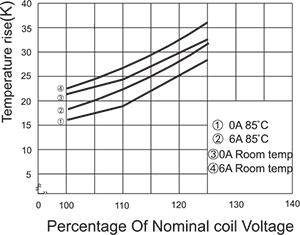
2) Please find coil temperature curve in the characteristic curves.
Ordering Information
| HAA03 | F | AB1 | DC | 24 | G – | S – | XXXX |
|---|---|---|---|---|---|---|---|
| Model | F:Class F Blank:Class B | AB1:1NO+1NC(Type 1) AB2:1NO+1NC(Type 2) 2C:2 Form C | Coil:DC | Coil Voltage | G:Gold plated Blank:No Gold plated | E:Flux Tight Type S:Sealed Type | Customer Code |
Notes:
1. PC board assembled with dust cover type and flux tight type relays can not be washed and/or coated.
2. Dust cover type and flux tight type relays can not be used in the environment with dust, or H2S, SO2, NO2 or similar gaseous environment etc.
Coil Data at 25°C
| Nominal Voltage VDC | Operate Voltage (Max.) VDC | Release Voltage (Min.) VDC | *Max. Allowable Voltage VDC | Coil Resistance Ω±10% |
|---|---|---|---|---|
| 5 | 3.80 | 0.50 | 7.50 | 35.7 |
| 6 | 4.50 | 0.60 | 9.00 | 51 |
| 9 | 6.80 | 0.90 | 13.50 | 116 |
| 12 | 9.00 | 1.20 | 18.00 | 206 |
| 15 | 11.3 | 1.50 | 22.50 | 321 |
| 18 | 13.5 | 1.80 | 27.00 | 483 |
| 21 | 15.8 | 2.10 | 31.50 | 630 |
| 24 | 18.00 | 2.40 | 36.00 | 823 |
| 36 | 27.00 | 3.60 | 54.00 | 1851 |
| 40 | 30.0 | 4.00 | 60.00 | 2286 |
| 48 | 36.00 | 4.80 | 72.00 | 3291 |
| 60 | 45.0 | 6.00 | 90.00 | 5142 |
| 80 | 64.0 | 8.00 | 120.0 | 9143 |
| 110 | 82.5 | 11.00 | 165.0 | 17285 |
Note:”*Max Allowable Voltage”: The relay coil can endure max allowable voltage for a short period time only.
Coil
| Coil Power | 700mW |
|---|
Safety Approval Ratings
| UL&CUL | N.O.:8A/6A 277VAC/250VAC/240VAC/125VAC, on/off 1s/9s, 85°C, 1×10⁵OPS N.O.:8A/6A 30VDC, on/off 1s/9s, 85°C, 1×10⁵OPS N.C.:6A 277VAC/250VAC/240VAC/125VAC, on/off 9s/1s, 85°C, 1×10⁵OPS N.C.:6A 30VDC, on/off 9s/1s, 85°C, 1×10⁵OPS N.O./N.C.:1A 24VDC, on/off 1s/1s, 85°C, 1×10⁵OPS N.O.:Pilot duty A300/240VAC, on/off 1s/9s, 70°C, 5×10⁴OPS N.O.:Pilot duty B300/240VAC, on/off 1s/9s, 70°C, 12×104OPS N.C.:Pilot duty B300/240VAC, on/off 9s/1s, 70°C, 1.5×10⁴OPS |
|---|---|
| TüV | N.O.:8A/6A 277VAC/250VAC/240VAC/125VAC, 85°C, 1×10⁵OPS N.O.:8A/6A 30VDC, 85°C, 1×10⁵OPS N.O.:4A 60VDC, 85°C, 1×10⁵OPS N.C.:6A 277VAC/250VAC/240VAC/125VAC, 85°C, 1×10⁵OPS N.C.:6A 30VDC, 85°C, 1×10⁵OPS N.O./N.C.:1A 24VDC, on/off 1s/1s, 85°C, 1×10⁵OPS N.O.:3A 240VAC(AC-15), 55°C, 5×10⁴OPS N.C.:1.5A 240VAC(AC-15), 55°C, 5×10⁴OPS N.O.:3A 24VDC(DC-13), 55°C, 5×10⁴OPS N.C.:1A 24VDC(DC-13), 55°C, 5×10⁴OPS |
| CQC | N.O.:8A/6A 277VAC/250VAC/240VAC/125VAC, 85°C, 5×10⁴OPS N.O.:8A/6A 30VDC, 85°C, 5×10⁴OPS N.C.:6A 277VAC/250VAC/240VAC/125VAC, 85°C, 1×10⁵OPS N.C.:6A 30VDC, 85°C, 1×10⁵OPS N.O./N.C.:1A 24VDC, on/off 1s/1s, 85°C, 1×10⁵OPS |
NOTES:
1. All values without specified temperature are at 25°C.
2. The above lists the typical loads only. Other loads may be available upon request.
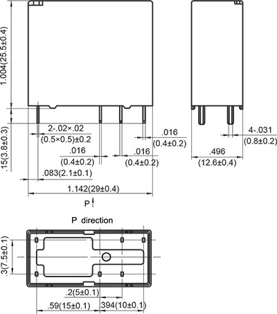
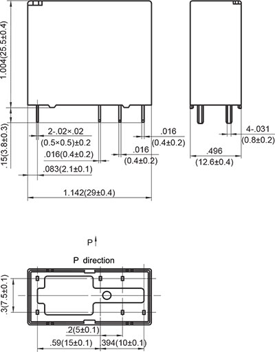
OUTLINE DIMENSIONS, WIRING DIAGRAM AND PC BOARD LAYOUT. Unit: inch(mm)
Outline Dimensions
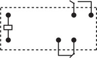
2C

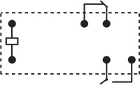
Wiring Diagram
(Bottom view)

PCB Layout
(Bottom view)
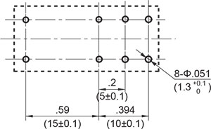
* The tolerance without indicating for PCB layout is always ±0.1mm.
Outline Dimensions
AB1
Wiring Diagram
(Bottom view)
PCB Layout
(Bottom view)

* The tolerance without indicating for PCB layout is always ±0.1mm.
Outline Dimensions
AB2
Wiring Diagram
(Bottom view)
PCB Layout
(Bottom view)
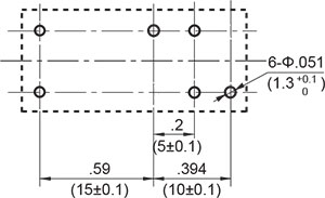
* The tolerance without indicating for PCB layout is always ±0.1mm.
Unless otherwise specified tolerances are:
| ≤1mm | >1mm and ≤5mm | >5mm |
| ±0.2mm | ±0.3mm | ±0.4mm |
CHARACTERISTIC CURVES
COIL TEMPERATURE RISE
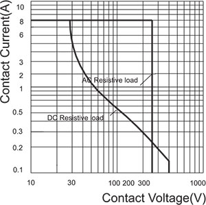
LOAD BREAKING CAPACITY
ELECTRICAL ENDURANCE
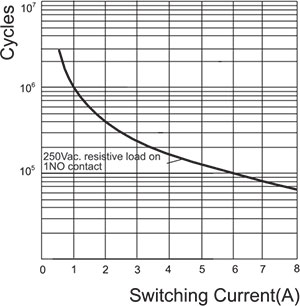
Test conditions:
1NO, Resistive Load, 250VAC,
Room temp., 1s on 9s off.
The data shown above are typical values.
PACKAGING SPECIFICATION
| BLISTER BOX | OUTER CARTON | OUTER CARTON SIZE |
|---|---|---|
| 40PCS | 800PCS | L400mm*W400mm*H190mm |
APPLICATION GUIDELINES
Automatic Wave Soldering
* Wave solder is the optimum method for soldering.
* Adjust the level of solder so that it does not overflow onto the top of the PC board.
* Unless otherwise specified, solder under the following conditions depending on the type of relay.
| Preheat time 20°C-100°C | Rising slope 20°C-120°C | Decreasing slope Peak-150°C | Slodering temperature 255°C-265°C |
|---|---|---|---|
| 90±5 seconds | <3°C/s | <4°C/s | 3~5s |
Hand Soldering
* Keep the tip of the soldering iron clean.
| Solder lron | 30W or 60W |
|---|---|
| lron Tip Temperature | Approx. 350°C 662°F |
| Solder Time | Within approx. 3 seconds |
* Immediate air cooling is recommended to prevent deterioration of the relay and surrounding parts due to soldering heat.
* Although the sealed type relay can be cleaned, avoid immersing the relay into cold liquid
(such as washing solvent) immediately after soldering. Doing so may deteriorate the sealing performance.
Discard the dropped product
![]()